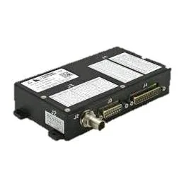
DBS-140U | USB 2.0 40 Mbps PCM Bit Sync / Decom / Simulator
- USB 2.0 peripheral with bit synchronizer, data decommutator, and simulator
- Bit synchronizer
- TTL, RS422 , LVDS or analog selectable data inputs
- NRZ-L/M/S or RNRZ-L input codes at rates 0.030 to 30 Mbps; BiØ-L/M/S input codes at rates 0.030 to 15 Mbps
- TTL, RS422 , LVDS or analog selectable data inputs
- Data decommutator/BERT
- Enhanced IRIG-106 Chapter 4 and Chapter 8 compatible
- Input rate up to 40 Mbps
- TTL, RS-422 or LVDS selectable external data and clock inputs
- Bit synchronizer internal input data and clock
- Onboard frame time tag – IRIG B, host time or elapsed
- PseudoRandom pattern receiver with error measurement: 7, 9, 11, 15, 20 or 23 type patterns
- Enhanced IRIG-106 Chapter 4 and Chapter 8 compatible
- Playback/simulator
- Regenerate archived PCM data at programmable rates of up to 40 Mbps
- Generate a programmable PCM format
- PseudoRandom pattern generator: 7, 9, 11, 15, 20 or 23 type patterns
- Provides all IRIG-106 PCM data outputs with coherent clock
- Regenerate archived PCM data at programmable rates of up to 40 Mbps
- IRIG-B time code reader and generator
- Windows compatible driver software included
- Supported by third party data analysis software
Hardware Datasheet:
[download id=”3540″]
Additional Information:
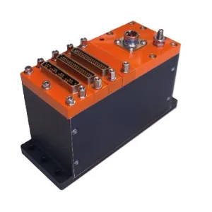
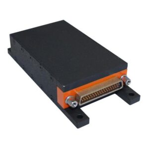
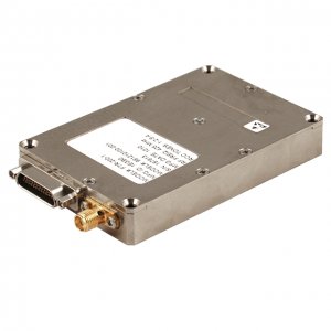
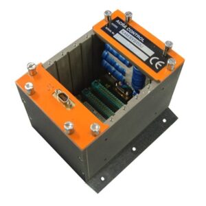
The DBS-140U combines the functions of a bit synchronizer, data decommutator and simulator into a USB 2.0 peripheral. Bit synchronizer functionality provides full-featured clock reconstruction, data recovery and code conversion. Recovered PCM data and clock are routed to a data decommutator, bit error rate tester and output multiplexer. The data decommutator provides full IRIG frame synchronization and data decommutation at rates up to 40 Mbps. PCM processed by the decom is selected by the user. Data and clock sources include the bit synchronizer output and external differential/single-ended receivers. Decommutated data words and time tags (elapsed, Host time or IRIG-B) are made available to the computer via the USB port for analysis, archival, and monitoring. The bit error rate tester provides closed loop link testing by measuring the errors in the bit synchronizer data output. A simulator function allows playback of archived data from the computer via the USB port, transmission of programmable PCM format data or generation of pseudo-random patterns. Simulator data and clock are routed to the output multiplexer. Selected output, bit synchronizer or simulator is buffered by differential and single-ended drivers.